Custom Buck Converter
Power Electronics
The Objective
For my Electronic Circuit Design course, I needed a custom power supply for a cooling fan. I designed and fabricated a custom step-down DC-DC buck converter PCB. I paired this with a 555 timer IC configured to generate a PWM signal, creating a fully integrated hardware fan controller with stable voltage regulation.
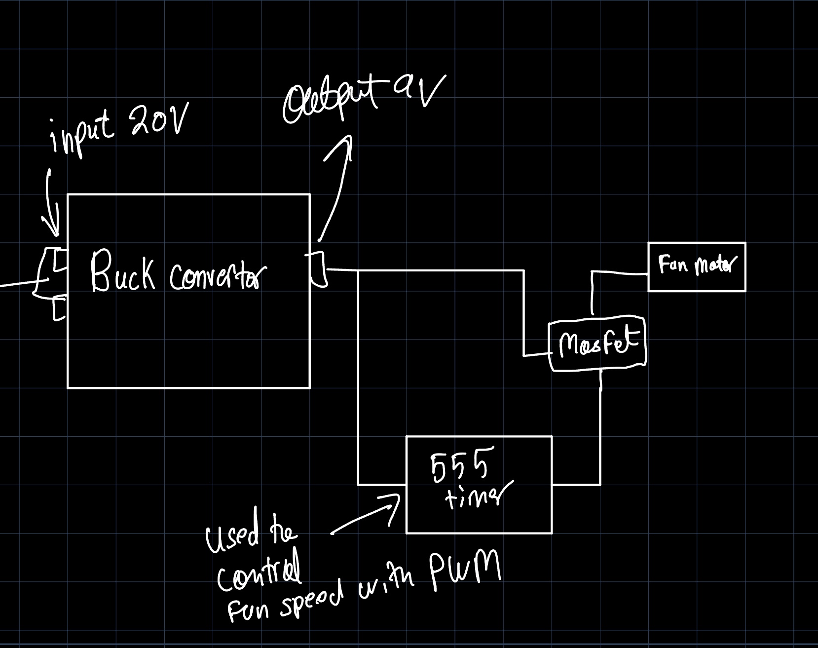
System Architecture Overview
Motor Speed Control
We initially developed a simple PWM controller using the 555 Timer IC to control the brightness of an LED. We then switched this logic to control the speed of the DC motor in our fan. The pictures of the controller are down below with the schematic and the soldered circuit. We use a potentiometer to control the PWM signal and an LED as an indicator of if the PWM signal is working. Another interesting note is that our switching rate was in the audible range, and hence in the video you can actually hear the switching of the 555 timer's PWM signal.
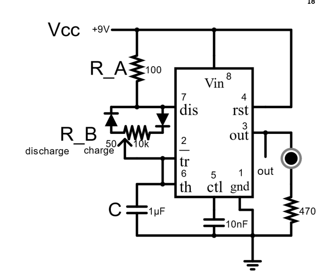
Motor Speed/LED Controller Schematic
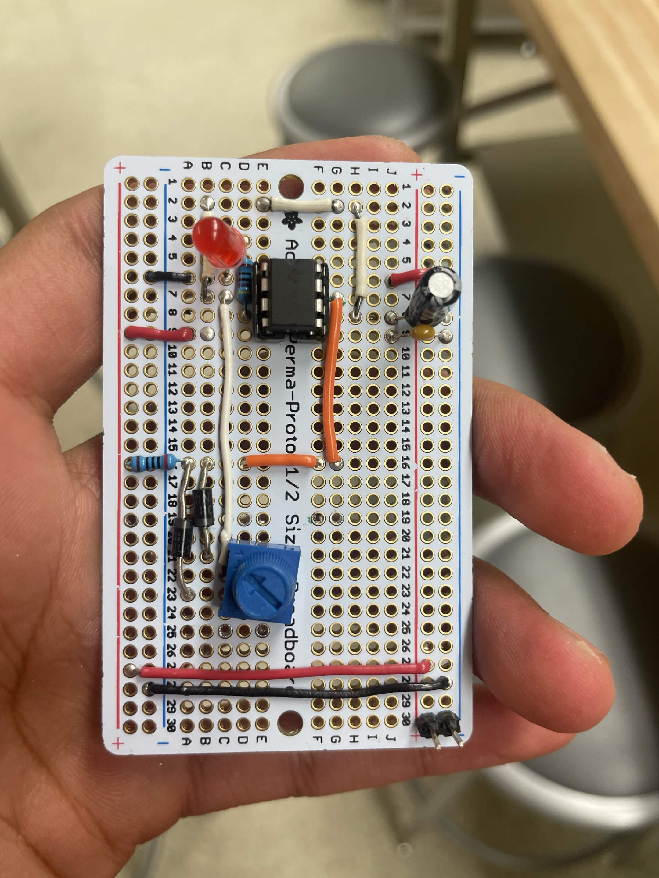
Motor Speed/LED Controller Circuit Soldered
The Architecture
In the class we studied the 555 Timer so that was our main control source for controlling the switching rate. This project required the use of decoupling capacitors to reduce noise and voltage ripple. I learned how to design PCBs for the first time and my board also miswired the MOSFET (so my solution was to route the cables myself to a new MOSFET). The overall project involved a controller for the fan's speed and then the buck converter itself for the conversion of 20V to 9V.
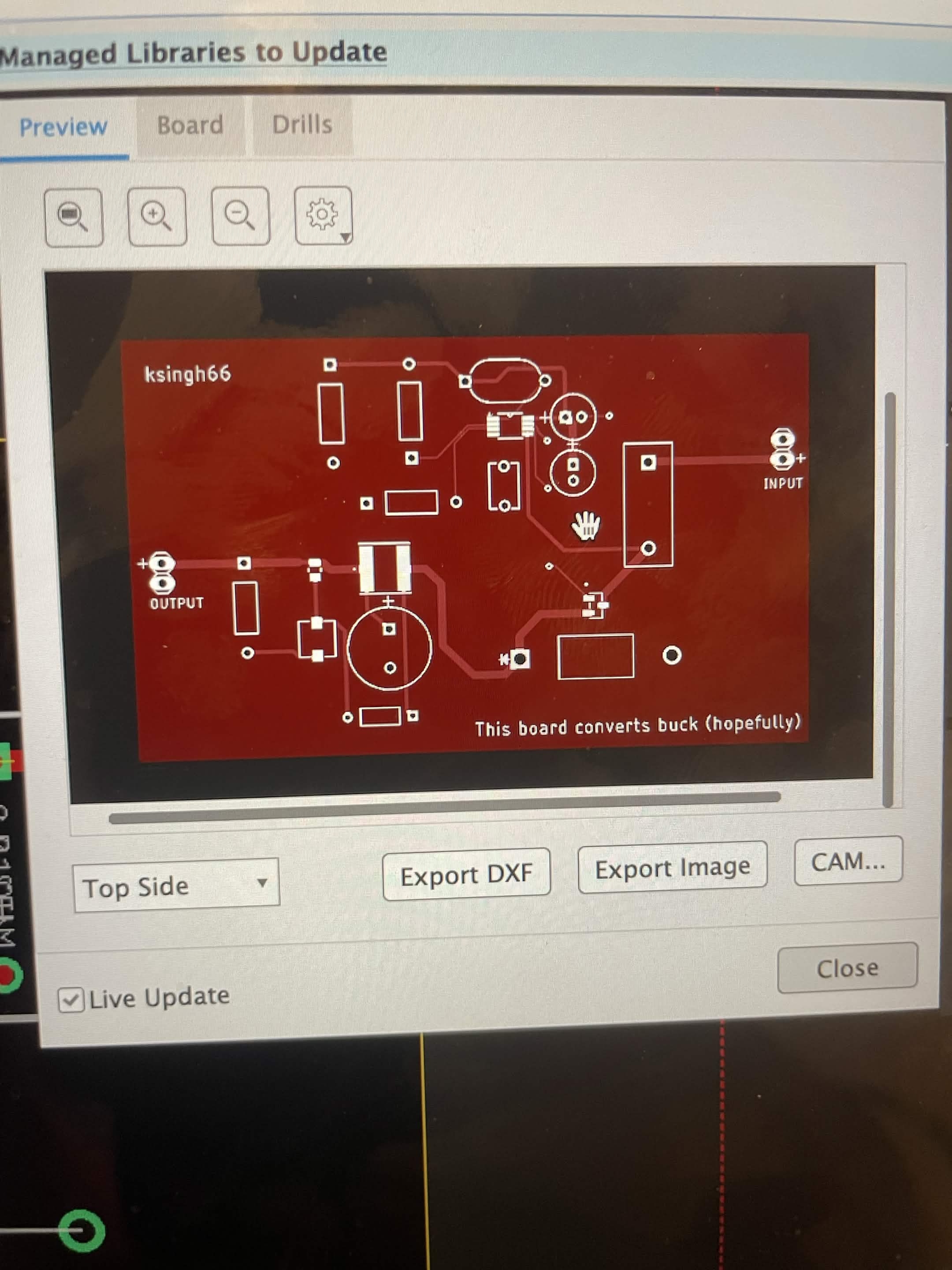
Buck Converter PCB Layout
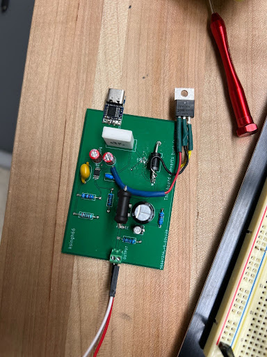
Buck Converter PCB