NEMA 17 Cycloidal Drive
Transmission & Actuator Optimization
The Objective
I built this to test the performance limits of a purely 3D-printed cycloidal drive. Initially, I designed it as an actuator for a custom robotic arm project and I had designed a fixed stator design which I later migrated to a fixed pins design. After a lot of prototyping, I realized the inherent backlash in 3D-printed cycloidal gears was too high for the precision I needed for my arm. I eventually scrapped the drive in favor of a belt-drive system for the arm, which yielded vastly superior repeatability. Even though it didn't make the final cut, the cycloidal design was a great exercise in mechanical tolerances and theoretical zero-backlash kinematics.
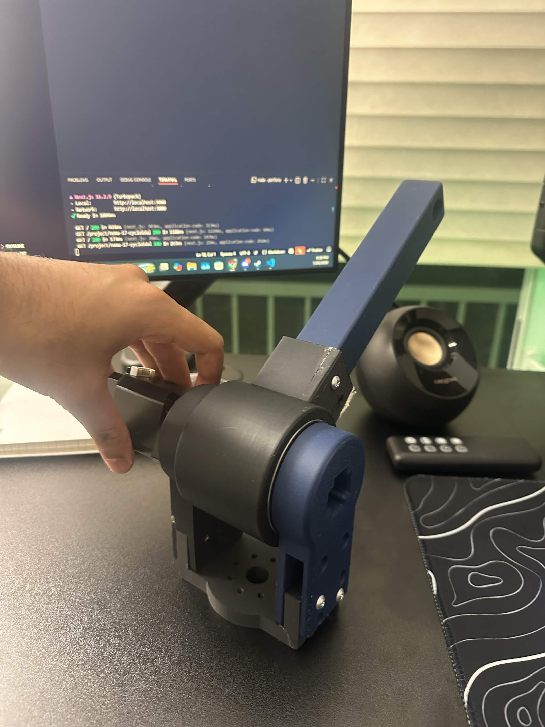
Print assembled
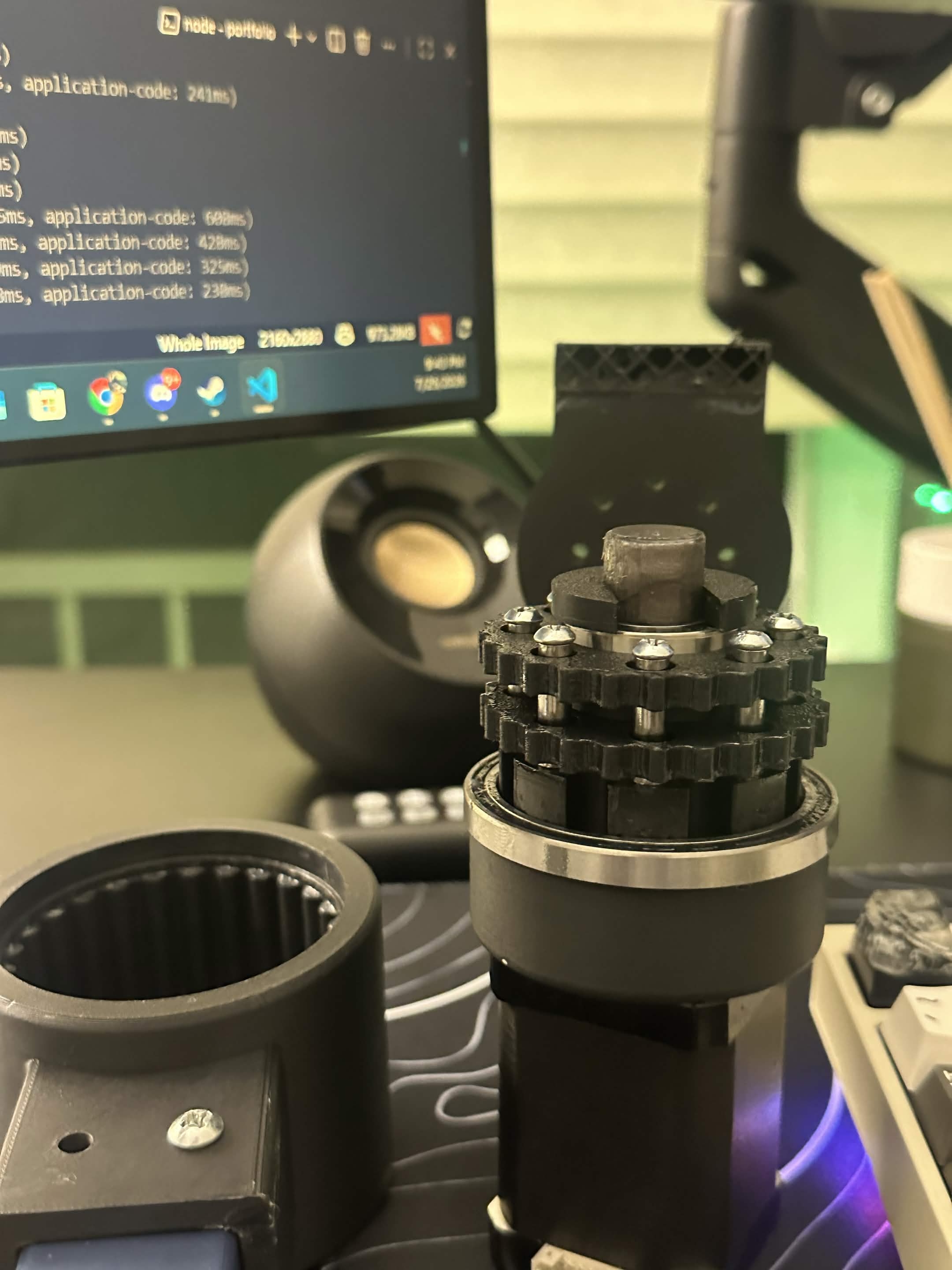
Side view of the opened assembly
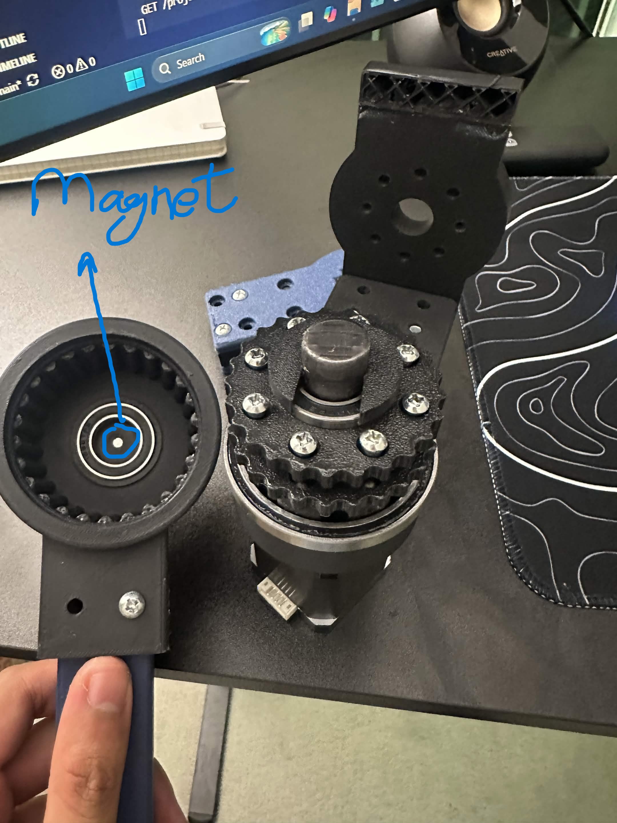
Top view of the opened assembly
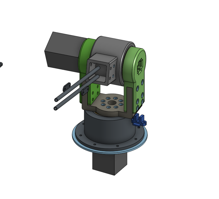
3D model design
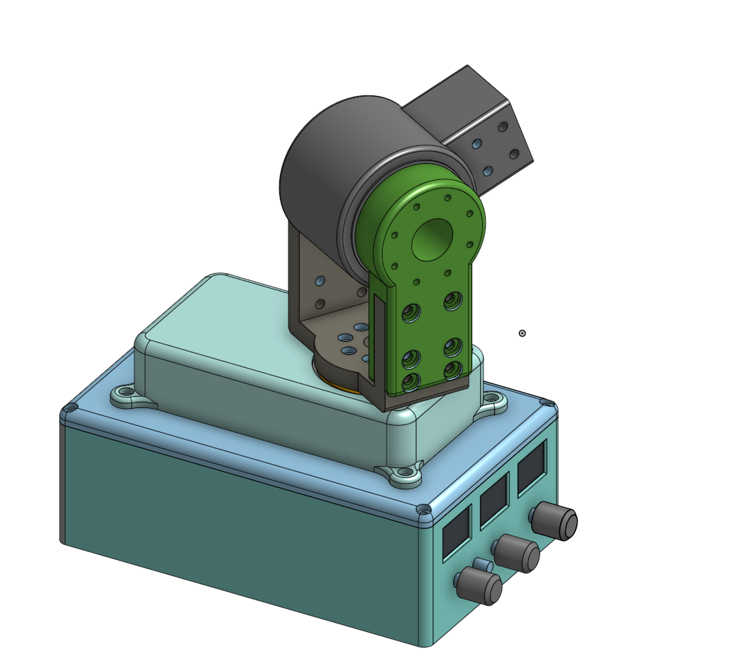
Alternative angle
Technical Approach & Testing
The absolute encoder was integrated into the design by being mounted on the stator arms holding the joint still, while the magnet was press-fit onto the rotor (of the gearbox, not the motor) itself. You can actually see the magnet for the encoder in the 'Top view of the opened assembly' picture (showing the outer rotor gear teeth). My torque tests pointed to a very fundamental issue with the gearbox and that was teeth slippage. The dimensions of the gearbox needed to be incredibly accurate for the task, and as soon as any real load was applied my gearbox would slip quite easily. I tried to solve this issue by increasing the area of contact between the teeth and also raising the gear ratio; however, these changes limit other areas of concern like actuator speed and size of the actuator. Additionally, the backlash was still present in the gearbox and it was only getting worse over time due to wear and tear on the plastic teeth.
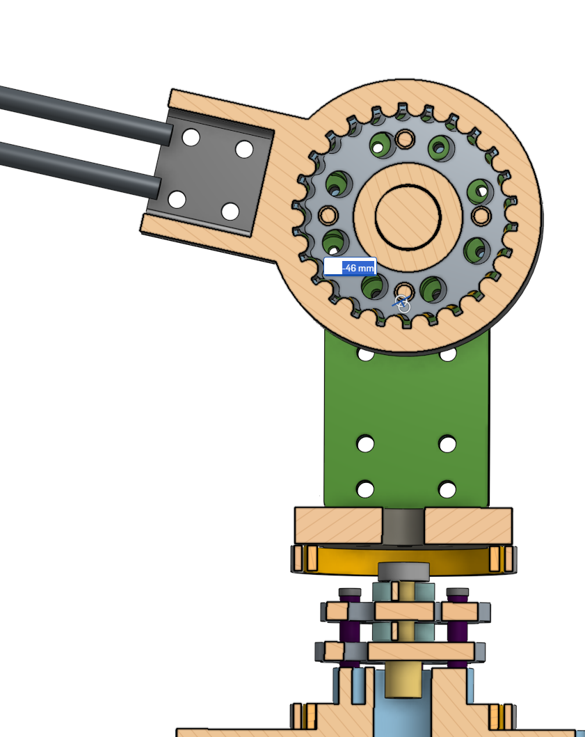
Cross-sectional View